

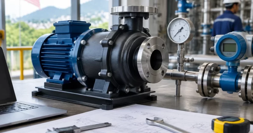
Magnetic drive (mag-drive) pumps are widely used for corrosive chemical transfer because the magnetic coupling eliminates the dynamic shaft seal and reduces leak risk. However, they are less forgiving of poor sizing than many sealed centrifugal pumps: limited NPSH margin, unexpected viscosity, or incompatible materials can quickly show up as low flow, overheating, or premature wear.
This step-by-step guide is for engineers and maintenance teams evaluating Magnetic Drive Pumps Malaysia for acids, alkalis, solvents, and other aggressive liquids. Use it to define the duty point, verify suction conditions, correct for real fluid behavior, and prepare a clear RFQ/spec for suppliers.
Step 1: Gather the minimum process data (don’t size from guesses)
Collect the core inputs before looking at pump curves. Sizing from assumptions often leads to oversizing, which can create recirculation, heat rise, and unstable operation—especially in mag-drive designs that rely on the pumped liquid for internal cooling and lubrication.
- Liquid name and concentration (and contaminants/solids if any).
- Operating temperature range (min/normal/max) to capture density, viscosity, and vapor pressure changes.
- Required flow rate (normal and min/max; include turndown needs).
- Tank levels and elevations: suction level range, pump centerline elevation, discharge destination level.
- Piping and equipment: suction/discharge sizes, approximate lengths, fittings, isolation/check/control valves, strainers/filters, and flowmeter type.
- Process constraints: batch transfer time, maximum discharge pressure, deadhead potential, throttling strategy.
- Site constraints: power supply, area classification (if applicable), footprint, access for maintenance.
Tip: For replacements, don’t size only from the old nameplate. Document what changed (chemical, temperature, pipe routing, valves, instruments) to avoid repeating the same failure mode.
Step 2: Define the flow rate and operating profile
Size to how the pump will actually operate. Many transfer duties are driven by time-to-transfer rather than steady flow.
2.1 Determine the duty flow
- Continuous service: size around the normal operating flow with realistic variation.
- Batch transfer: flow = volume / target transfer time (add line-fill or end-of-batch allowance if needed).
- Multiple destinations: identify worst-case (highest head) and best-case (lowest head) routes to avoid operating too far left/right on the curve.
For centrifugal mag-drive pumps, aim to run near the best-efficiency region. Prolonged low-flow operation can increase internal recirculation and heat, accelerating wear.
Step 3: Calculate Total Dynamic Head (TDH) step-by-step
TDH is the head the pump must add at the required flow. Break it into:
- Static head (elevation difference between suction and discharge liquid levels)
- Pressure head (pressurized/vacuum vessels or headers)
- Friction losses (piping, fittings, valves, strainers, instruments)
3.1 Static head
Use worst-case levels for sizing: lowest suction level and highest discharge level.
3.2 Pressure head (closed tanks, reactors, pressurized headers)
Convert pressure difference between suction and discharge vessels to head (or keep everything in pressure units until you read the curve). Consistency matters more than the unit choice.
3.3 Friction losses and “hidden” restrictions
Friction losses rise with flow and often dominate TDH on long or small-bore lines. Include realistic losses for:
- Pipes and vertical risers
- Elbows, tees, reducers, hoses/flexible connectors
- Isolation valves (especially if not fully open)
- Check valves
- Strainers/filters (use dirty allowance if plugging is credible)
- Flowmeters and other inline instruments
- Control valves (use intended operating ΔP, not just max rating)
Practical check: If friction seems unusually high, verify actual internal diameter (schedule, lining, and hose IDs are common surprises).
Step 4: Verify NPSH available (NPSHa) with margin
NPSH is a common failure point in mag-drive applications. Cavitation damages any centrifugal pump, and vapor formation can also upset internal clearances and cooling paths in mag-drive designs.
- NPSHa is set by the system (suction pressure/level, vapor pressure, suction losses).
- NPSHr comes from the manufacturer’s curve/test data.
4.1 Build your worst-case NPSHa case
Evaluate the condition that produces the lowest NPSHa, typically: highest temperature, lowest tank level, highest suction losses (dirty strainer/long run/many fittings), and highest flow. Compare that NPSHa to NPSHr at the same flow.
Avoid “NPSHa = NPSHr” selections. Real plants drift: temperatures swing, levels vary, and strainers foul.
4.2 Improve NPSH if it’s tight (before changing pump type)
- Increase suction pipe size and reduce suction velocity
- Shorten the suction run and remove unnecessary fittings
- Move the pump closer to the source (flooded suction is preferred)
- Lower the pump relative to the tank
- Consider a lower-speed option or alternative hydraulic selection (where available)
If adequate margin can’t be achieved, discuss alternatives with your supplier. Some services move to AODD pumps for suction tolerance, with different efficiency and pulsation tradeoffs.
Step 5: Correct for corrosive fluid properties (viscosity, SG, vapor pressure, solids)
Chemical properties affect hydraulics and reliability. Don’t assume water performance.
5.1 Specific gravity (SG) and power
Head (m) is largely SG-independent, but pressure and power rise with SG. Confirm motor kW and temperature limits, particularly where internal circulation provides cooling.
5.2 Viscosity and pump curve derating
Higher viscosity reduces flow/head/efficiency and increases power draw. Request viscosity-corrected performance from the supplier and confirm the corrected duty point still meets requirements.
5.3 Vapor pressure and flashing risk
High vapor pressure (common with solvents or hot chemicals) reduces NPSHa and increases cavitation/flashing risk. Treat vapor pressure as a primary sizing input.
5.4 Solids/crystals and internal wear
Many mag-drive pumps have close clearances at bushings and thrust surfaces. If the liquid can crystallize, precipitate, or carry abrasives, define a realistic strainer/maintenance approach, specify wear-resistant internal materials where appropriate, and consider whether another pump type is better suited.
Step 6: Select materials and construction for chemical compatibility
Compatibility must cover all wetted components, not only the casing.
- Wetted materials: casing, impeller, backplate, containment shell, shafts/sleeves, bushings.
- Elastomers: O-rings and gaskets (e.g., PTFE, FKM, EPDM) matched to chemical and temperature.
- Containment shell: metallic vs non-metallic affects eddy-current heating and temperature limits; selection depends on fluid and duty.
When comparing Chemical Pumps Malaysia suppliers, provide the chemical name, concentration, and temperature range so they can propose a compatible build rather than a generic offering.
Step 7: Choose the pump model using the curve (and avoid common sizing traps)
Combine the prior steps into a clear duty point:
- Flow (normal and min/max if needed)
- TDH at that flow (static + pressure + friction with realistic allowances)
- NPSHa (normal and worst-case) vs the pump’s NPSHr
- Fluid properties (SG, viscosity, temperature, vapor pressure)
- Materials for corrosion resistance and wear risk
7.1 Where to place the duty point
Avoid selecting a pump that normally operates at the extreme left (very low flow) or extreme right (runout) of the curve. A stable operating region reduces heat rise, vibration, and internal wear.
7.2 Confirm motor power and thermal limits
Verify absorbed power at the duty point (including viscosity correction) and select adequate motor margin. Also confirm the pump’s temperature and dry-run limits. If deadhead is possible, consider safeguards such as a bypass/minimum-flow line (when safe), discharge pressure/flow interlocks, and clear operating procedures.
7.3 Check system interaction (control valve, multiple branches)
Throttling moves the operating point along the curve. Confirm minimum continuous flow and NPSH remain acceptable across expected operating conditions.
Step 8: Turn the sizing into a clear RFQ and commissioning checklist
Include enough detail to let suppliers quote and size consistently:
- Duty flow (normal/min/max) and TDH breakdown (static/pressure/friction)
- NPSHa normal and worst-case, plus your NPSH margin expectation
- Full fluid data: chemical, concentration, temperature range, SG, viscosity range, vapor pressure (if known)
- Wetted materials and elastomers
- Nozzle/connection sizes, flange standard, and orientation constraints
- Motor supply details (voltage, frequency, efficiency class if required)
- Instrumentation needs and test/acceptance expectations
- Recommended spares (bushings, O-rings, containment shell, impeller)
At commissioning, focus on fundamentals that affect reliability: correct rotation, proper priming/flooded suction, fully open suction valve, clean strainers, no air leaks on suction, and verification of actual flow and differential pressure. Record baseline amps, temperatures, pressures, and vibration for future troubleshooting.
Useful next reads (related pump options)
- Chemical pump options for industrial transfer duties
- Air Operated Double Diaphragm Pumps for challenging suction or intermittent service
- Specialty pumps and flow-related equipment for niche chemical applications
Conclusion
Sizing a mag-drive pump for corrosive chemical transfer is best handled as a structured workflow: define the real flow requirement, calculate TDH with all losses, confirm NPSHa with margin, correct for SG/viscosity/vapor pressure, and specify chemically compatible materials. Presenting this information clearly helps suppliers select a reliable mag-drive model and reduces common problems such as cavitation, overheating, and unstable low-flow operation.
If you want a quick verification before purchase, a short review of your duty point, suction layout, and fluid data often prevents costly rework after installation.
Frequently Asked Questions
What information do I need to size a mag-drive pump for corrosive chemical transfer?
At minimum: required flow (normal and range), suction and discharge vessel levels/elevations, any vessel pressures, suction/discharge piping sizes and approximate layout (lengths, fittings, valves, strainers/filters), chemical name and concentration, operating temperature range, and any known viscosity/SG/vapor pressure. With those inputs, a supplier can calculate TDH, check NPSH, and propose suitable materials and model options.
How much NPSH margin should I allow for a mag-drive pump?
You should plan for a practical margin between NPSH available (NPSHa) and NPSH required (NPSHr) because real systems change over time (fouled strainers, lower tank level, higher temperature). The best margin depends on how critical the service is and how stable suction conditions are, so discuss the target margin with your pump supplier—but avoid selections where NPSHa only barely equals NPSHr at the duty point.
Can I use a mag-drive pump for high-viscosity or solvent service?
Often yes, but you must apply viscosity corrections to the pump curve and confirm power draw, efficiency, and temperature limits. For solvents or hot chemicals with high vapor pressure, NPSH becomes especially important. Share the viscosity range and temperature range with your supplier so they can derate performance properly and verify internal cooling/lubrication suitability.
What’s the difference between a mag-drive pump and a diaphragm pump for chemical transfer?
A mag-drive pump is typically a centrifugal chemical pump that uses a magnetic coupling instead of a dynamic shaft seal, giving smooth flow and good efficiency in many transfer duties. An air operated double diaphragm pump (AODD) is a positive displacement pump driven by air, which can be helpful for certain suction-lift or intermittent applications and for handling some solids, but it produces pulsating flow and has different air/utility considerations. The right choice depends on your chemical, required flow/head, suction conditions, and plant utilities.
Do I need a vertical pump or multistage pump instead of a mag-drive pump?
Not necessarily. A vertical pump may be used when you need a specific installation arrangement (such as sump or tank-mounted configurations) or to improve suction conditions. A multistage centrifugal pump is typically chosen when very high head is required at moderate flow (common in some industrial water pump services). For corrosive chemical transfer, a mag-drive pump is often selected for leak-risk reduction, but final selection should be based on duty head/flow, NPSH, materials, and layout constraints.
Need help sizing a mag-drive chemical pump for your plant?
M.E.T. Motion Engineering & Trading Sdn. Bhd. supports Malaysian plants with end-to-end pumping solutions—from pump diagnostic and consulting through selection, complete pump system fabrication, installation, and after-sales maintenance.
If you share your flow, piping layout, tank levels, and chemical details, our technical team can help you validate TDH and NPSH assumptions, recommend suitable magnetic drive pump configurations and materials, and propose practical safeguards for reliable corrosive chemical transfer.
